

However, one of the key contributing factors to the lifetime of products with high power efficiency, high frequency is “heat management.” DEKRA iST finds that there are three key factors highly associated with “thermal management” – thermal resistance (Rth or Tr), intermittent operating life test (IOL), and safe operating area (SOA).
Thermal resistance (referred to as Rth or Tr)
As Wide Bandgap has greater power efficiency, it plays an important role in thermal analysis before Rth is put to reliability testing. The Rth test result can be used to observe the changes in thermal resistance of structural layers and chip temperature changes. Suitable testing conditions and environment will be configured prior to a reliability test, and the difference between structural layers will be determined after the test.
The below figure is Rth Structure Function. It is notable that results may vary in light of different composition in products and different measurement methods. DEKRA iST has conducted several tests of measurement and made comparison by selecting and stacking specific curves for detailed observation. This way, the personnel can further check if the structural layer of a product is normal.
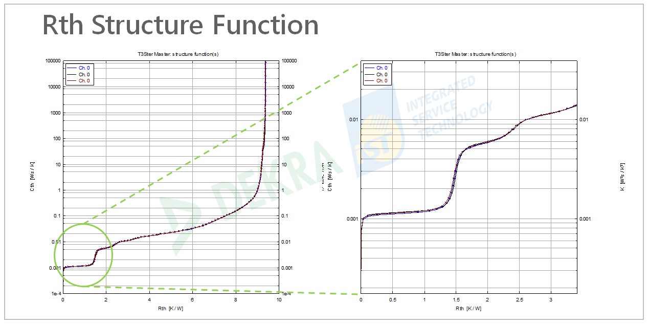
Figure 1: Rth Structure Function
Reference: DEKRA iST
Reference: DEKRA iST
Intermittent Operating Life Test (referred to as IOL)
WWide Bandgap is known for its great power efficiency and high frequency, with a variety of applications in the automotive field. Currently IOL testing is predominantly in line with AEC-Q101 and LV324 (AQG324). The former is adopted at component level, while the later is applicable to module level. IOL testing is a type of dynamic reliability test method. Based on the chip temperature, the changes in high temperature and low temperature (temperature cycling) generated from the simulation of product on/off (power cycling) are used to characterize the lifetime, product reliability, and the moment when an abnormality occurs.

Figure 2: IOL testing profile
Reference: DEKRA iST
Reference: DEKRA iST
Safe operating area (referred to as SOA)
The safe operating area (SOA) is defined as the voltage and current conditions over which the power semiconductor devices, such as bipolar transistor, field effect transistor, thyristor, and insulated gate bipolar transistor, can be expected to operate without self-damage. Users check if a product runs at the rated voltage/ current and is not over heated through its SOA, in order not to work beyond the SOA conditions and cause failure.
There are five elements that define a SOA: Tj max, Rds on, Vds max, Ids max, and Rthj-c. DEKRA iST took electrical parameters, coupled with thermal resistance, proposing a SOA that is worth implementing. It can not only significantly shorten time, but also minimize the damage and loss to a product under testing. In the meantime, it accelerates the development at a lower cost, improving the product’s competitiveness with faster time-to-market (TTM). The below figure shows the SOA case examples of DEKRA iST.
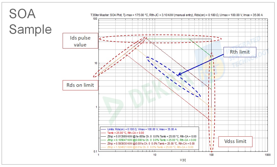
Figure 3: SOA Sample
Reference: DEKRA iST
Reference: DEKRA iST
To make all your PROBLEMS SOLVED, we provide professional consultant and service.
For more information or service, please feel free to email to 📧 sos@dekra-ist.com


